Capacitors Lab
last updated Sept. 18, 2002

home | notes menu

P re-lab:
The pre-lab and the instructions for the pre-lab are located at http://www2.hawaii.edu/~jmcfatri/labs/capsprelab.html . The pre-lab is due at the beginning of the class. One pre-lab is due per group.

Objectives
The objectives of this lab are:
1) to create a capacitance meter
2) to determine the capacitance of capacitors in series and parallel
3) to measure the capacitance of a homemade capacitor

Notes on Chapter 7
pp 43 - 46 of your lab book


1. Capacitors:
A capacitor is a circuit element which stores charge. Anything that stores charge is a capacitor. You are a capacitor! (If you weren't, you wouldn't be able to scuff your feet on carpet and zap your friends!)  You have a capacitance of about 100 pF (100 x 10 -12 F). For all capacitors, there is a value which describes how much charge can be put on a capacitor, called capacitance.  Capacitance is measured in Farads (F = C / V).
Capacitance is the amount of charge (Q) stored in a capacitor per unit voltage (V): C = Q / V

2. The parallel plate capacitor:
The simplest type of capacitor is the parallel plate capacitor. A parallel plate capacitor is comprised of two metal plates separated by a distance, d, and which has a voltage difference, V, between them. We can describe this capacitor analytically.(Other capacitors are much more complex!)
We can determine quite easily with the equations that we've learned so far that the capacitance of a parallel plate capacitor is:
C = kepsilon 0A / d
where A is the area of the plate, epsilon 0 is the permittivity of free space = 8.85 x 10 -12 F / m, and k is the dielectric constant. If there is no material between the plates of a capacitor (a vacuum) then k is 1. You will learn about dielectrics in your lecture class; in the lab all you need to know is that a dielectric increases the capacitance of a capacitor (i.e. k > 1).

3. Capacitors in Alternating Current circuits:

In an AC circuit, a capacitor acts like a resistor. Energy is lost as the electric fields of the capacitors are created and destroyed.  We can treat the capacitors as resistors with a resistance of: X = 1/omega C, where omega is the angular frequency of the AC voltage source. Instead of resistance, we call this quantity the reactance of the capacitor .
4. Capacitors in series and parallel:
You can add resistances in series and parallel; the same rules apply for reactances:
series: Xeff = X1 + X2
parallel:1/Xeff = 1/X1 + 1/X2
You can substitute in the definition of the reactance of a capacitor into the above equation to get:
series:
  1
=
 1
+
  1  
Ceff
C1
C2

parallel: Ceff = C1 + C2

We will verify these two equations in our experiment.
5. The Bridge Circuit:
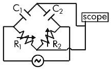
The Bridge Circuit we are using in this experiment is one way to find the capacitance of an unknown capacitor. The unknown capacitor in the circuit is C2, as labeled in the circuit diagram in the procedure and in your pre-lab. You know now that a capacitor acts like a resistor in an AC Circuit. So we will first analyze the behavior of resistors in the bridge circuit, then later replace the resistors with capacitors. Then our circuit will look like the picture below.
caps circuit with resistors
Now let's use Kirchhoff's Voltage Rule to find R4, which replaces the unknown capacitor. Let's go through two loops. The first loop, which I will call "top" starts at the battery, goes through R3 , then through R4 then back to the battery. The second loop, which I will call "bottom" starts at the battery, goes through R1 and then through R 2 and back to the battery. I will also make an important assumption: I assume that the resistance of the oscilloscope, like all voltmeters, is very high and therefore no current goes through it.
"top" equation: V0 - ItopR3 - I top R4 = 0
"bottom" equation V0 - IbottomR1 -Ibottom R2 = 0
Rearranging gives:
Itop = V0/ (R3+R4)
Ibottom = V0/ (R1 + R2)
.
Now let's find the voltage difference that the oscilloscope sees. We will call VA the voltage at the top (where the oscilloscope is connected) and VB is the voltage at the bottom.
VA = V0 - ItopR3 = V 0 - (V0R3) / (R3 + R4 )
VB = V0 - IbottomR1 = V 0 - (V0R1) / (R1 + R2 )
VA - VB is the voltage difference. That doesn't seem to help us get the R4, which is what we want to find. But remember that R1 and R2 are variable resistors. We can make their value anything we want. Maybe we can't solve this problem in general, but we can solve the problem for a specific case. Let's suppose we change R1 and R2 until VA = VB . Then the voltage difference is zero, and you will see a 0 V reading on the oscilloscope. Then
(V0R3) / (R3 + R4) = (V 0R1) / (R1 +R2)
Solving this, I get
R4 = R3 (R2 / R1)
Now instead of resistance, let's put the reactance of the capacitors. (R3 = X1, R3 = X2). Solving this new equation for C2, you get:
C2 = C1 (R1 / R2)
and now we have a capacitance meter, because we can find C2 if we know C1, R1, and R2

Procedure:
Part I: Measuring capacitance
1) The circuit below is already constructed for you.  You only need to connect the oscilloscope and the frequency generator (as in your pre-lab).  C1 = 0.22 µF.
circuit diagram
2) Attach capacitor A to the circuit.

3) Vary the two resistances R1 and R2 by turning the black knobs on the box. Do this until the amplitude of the output on the oscilloscope is minimized (nearly flat line). You need to put your oscilloscopes on a more sensitive scale to see this (in the mV range at least!)

4) Disconnect the scope and the frequency generator, being careful not to change the value of the resistors.  Measure the two resistances with a digital multimeter.

5) Determine the capacitance of A. C2 = C1 * (R 1 / R2).

6)
Repeat for capacitors B - E.

Part II: 
Effective Capacitance of Capacitors in Series and Parallel
1)  Using your measured values for A and B, analytically determine the effective capacitance of A and B when they are placed in series. 

2) Connect A and B in series.  Repeat part I, steps 1-5, but instead of attaching capacitor A, attach the "A series B" capacitor. This is the experimentally determined the effective capacitance of A in series with B.

3) Repeat for A and B in parallel.

Part III:  Homemade Capacitor 

The homemade capacitor is a capacitor made out of two sheets of aluminum foil with a transparency between them.  The capacitance of our homemade device is very small (~10 nF).  To determine the capacitance, we will have to make our capacitance meter more sensitive.

1) Pick the smallest capacitor from part I and connect them in series to the orginal C1. These two capacitors are now the new C 1. Camke sure your oscilloscope is attached to the end of the new C 1, not the old one.

2) Using your modified capacitance meter, find the capacitance of the homemade capacitor.

Important! To measure the capacitance of the homemade capacitor, you will have to touch the leads to either side of the homemade capacitor.

Data:
Part I: Creating and Testing a Capacitance Meter

Capacitor Code
R1
(    )
R2
(    )
C2
(    )
C2 expected
(    )
A


B


C


D


E


Part II:Series and Parallel
Capacitor Configuration
R1
(     )
R2
(     )
C2
(     )
C2 expected
(     )
A series B


A || B


Part III Homemade Capacitor:
assume d = 0.006 cm
measure length of foil: _____________±___________
measure width of foil: _____________±____________
Capacitor
R1
(     )
R2
(     )
Chomemade
C1 not 0.22 µF
(     )

homemade


Assignment:

1.  What is the value of k for our homemade capacitor? (Show your work)


2.  If I add a capacitor (C1) in series to another (C2), will I increase or decrease the capacitance of the overall circuit?  Justify your answer.


3.  If I add a capacitor in parallel to another, will I increase or decrease the capacitance of the overall circuit?  Justify your answer.