 This exercise is designed to help
you understand how to operate the equipment used in the Capacitors
lab. Read the selection below and answer the questions at the end.
This exercise is designed to help
you understand how to operate the equipment used in the Capacitors
lab. Read the selection below and answer the questions at the end.
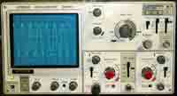
Circuit
Element
Photo
of Element
Circuit
Symbol
Description
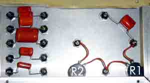
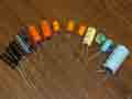
Capacitor
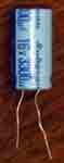
Capacitors
are circuit elements which store charge. Capacitance, the amount of charge
that a capacitor can store per unit voltage, is measured in Farads (F).
The capacitance of a capacitor is typically printed on the capacitor.
If you would like to see capacitors charging up in a circuit, see the applet at:
If you would like to see capacitors charging up in a circuit, see the applet at:
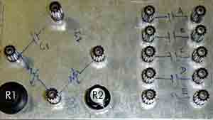
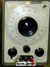
Potentiometer
(pot.)
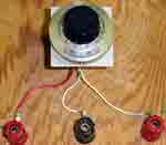
A potentiometer
is a variable resistor.
The potentiometer to the left has a dial attached to it, but the capacitors
lab has knobs instead.
Potentiometers have three leads. The first two leads are one resistor, the second lead and the third lead are another resistor. Usually the total resistance is fixed, but the ratio of the two resistances changes as you turn the knob.
Potentiometers have three leads. The first two leads are one resistor, the second lead and the third lead are another resistor. Usually the total resistance is fixed, but the ratio of the two resistances changes as you turn the knob.