N otes on Chapter
8
pp 73 - 91 of your lab book
Since we rarely deal with "point" particles in real life, we must strive to understand rotational motion. Unlike point particles, real objects (two or three dimensional objects) will spin or turn when an off-center force influences them. Such an "off-center force" is called a torque. It is a torque which we apply to a wrench to turn a nut, and a torque we apply to pedal our bicycles.
The next thing you must understand in order to learn about rotational motion is something called the moment of inertia.
Class participation: Which to you think has the greater moment of inertia, a ruler rotated about an axis going down its length or a ruler rotated about an axis which goes perpendicular through the face?
Once you have mastered these concepts, learning the rest of rotational kinematics is easy. Every equation in rotational kinematics has a linear analog which you already know, and it is easy to go from one to the other. (You may want to save this table for your lecture course! Note: 170 students please replace delta with infinitesimal change, d, such that v = dx/dt)
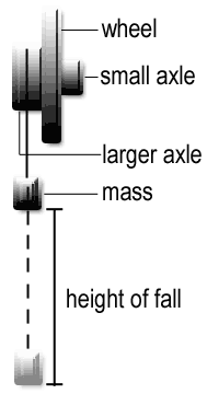
Now to the situation in our lab. We have three metal cylinders of different radii attached to one another. This is the object which we will be rotating. We will apply a torque to this object to get it spinning.
The torque we will apply ( applied)
will be caused by hanging a mass (m) on the cylinder. Another torque is
caused by friction (
friction).
applied)
will be caused by hanging a mass (m) on the cylinder. Another torque is
caused by friction (
friction).
pp 73 - 91 of your lab book
Since we rarely deal with "point" particles in real life, we must strive to understand rotational motion. Unlike point particles, real objects (two or three dimensional objects) will spin or turn when an off-center force influences them. Such an "off-center force" is called a torque. It is a torque which we apply to a wrench to turn a nut, and a torque we apply to pedal our bicycles.
The next thing you must understand in order to learn about rotational motion is something called the moment of inertia.
- The moment of inertia of a body is the body's resistance to changing its rotational motion.
Class participation: Which to you think has the greater moment of inertia, a ruler rotated about an axis going down its length or a ruler rotated about an axis which goes perpendicular through the face?
Once you have mastered these concepts, learning the rest of rotational kinematics is easy. Every equation in rotational kinematics has a linear analog which you already know, and it is easy to go from one to the other. (You may want to save this table for your lecture course! Note: 170 students please replace delta with infinitesimal change, d, such that v = dx/dt)
|
Rotational equation
or concept |
Linear Analog
|
Conversion from
linear to rotational |
|
moment
of inertia (I)
|
mass
(m)
|
|
|
torque
(
|
force
(F)
F = ma |
(where r is the distance from the center of mass to where the force is being applied) |
|
angular
displacement (
|
linear
displacement (s)
|
(where s = the arc distance) |
|
angular velocity
(
|
linear
velocity (v)
|
|
|
angular
acceleration (
|
linear
acceleration (a)
|
|
|
angular
momentum (L)
L = I |
linear
momentum (p)
p = mv |
|
|
rotational
kinetic energy (Krot)
K = 1/2 I |
linear
kinetic energy (K)
K = 1/2 mv2 |
|
Now to the situation in our lab. We have three metal cylinders of different radii attached to one another. This is the object which we will be rotating. We will apply a torque to this object to get it spinning.
The torque we will apply (
net torque
=
applied
-
friction
= I
Notice that
this equation is a linear eqaution. If you plot
applied vs.
then the slope
of this graph is the moment of intertia (I) and the y intercept is the frictional
torque (
friction).