(**special note: This lab has been significantly changed
from the book. The book procedure asks you to use a multimeter to measure
Vrms of the AC power supply. However, I determined over the course of
the summer that the rms value of the voltage reading is not accurate on the
multimeter for high frequencies. Certain settings on the multimeter
had a more pronounced error than others (the 0-2 V setting). Since the
emphasis of this class is on experimental methods (i.e. how to read a voltage,
current, etc.), I thought I should mention this. If you are ever required
to read a voltage with a high frequency, you should know that multimeters
are typically only accurate for 60 Hz. You should instead use an oscilloscope,
which is accurate even at MHz ranges. Our lab manual is being rewritten
as we speak. Isn't it nice to know that even your physics professors
and graduate students can mess up too every once in a while....)
The theory section of the Induction lab is well written. Please
read it! (pp. 67 - 68)
We will be verifying Lenz's Law and Faraday's Law in today's lab.
These laws are especially important since they are the fundamental concepts
behind the generation of electric current from turning wheels (i.e. the basis
of nearly all of our electrical power generation, with the sole exception
of solar cells!). These laws tell us what happens when we have a time-varying
magnetic field. Actually, we've already had a circuit with a time-varying
magnetic field: the RLC circuit! Since the current was changing with
time, the magnetic field was also changing with time. I mentioned that
the inductor "opposes the change in its magnetic field", but I never said
why. That's where the concept of induction (and our two
laws) comes in. Lenz's Law says:
The [induced] current flows in a direction such that
the magnetic field produced by the current opposes the change in flux which
induced the emf. -pg. 68
Lenz's Law is just a verbalization of Faraday's Law. Faraday's law
says the same thing, but in equation form:
emf = - change in flux / change in time
where flux = magnetic field strength * area of the loop * cos(angle between
the normal to the loop and the field)
That's basically all of the concepts you need for part I of today's
lab. I will go over some examples in class to help you understand the
concept, in case you haven't covered it in lecture yet
In part II, we will be looking at an LR Circuit to verify our
understanding of self-induction (L). But since we have already explored
RLC circuits ad nauseum, this part of the lab is just to drive in the last
nail. Now you should know why inductors work the way they do.
We've taken out the capacitor to make the circuit simpler and to take our
focus away from natural oscillations to the induction of our solenoid.
From our knowledge of the LR circuit we know that the impedance of the circuit
is Z = (R^2 + w^2*L^2) ^ 0.5. (Your lecturer may or may not lecture on impedance.
I will not cover it nor quiz you on it.). Thus the voltage on the resistor
is V_R = V0 * R / Z, where V0 is the maximum voltage from the AC power supply.
We will fit our data to this equation.
Procedure:
Part I: Verifying Lenz's Law and Faraday's Law
1. Lenz's Law : Before you do this part, you
should record what you expect to happen, based upon what you know
of Lenz's Law. (Fill out the questions on the data sheet).
2. Now that you have answered the questions, connect
the galvanometer to the solenoid. Stick the North end of the magnet
into the solenoid. Then, after the current has returned to zero, take
out the magnet. Record what you see.
3. Repeat step 2 with the South pole of the magnet.
4. Faraday's Law : Answer the questions and record what
you expect to happen in this section.
5. Stick the North end into the solenoid FAST.
Then, after the current has returned to zero, take out the magnet FAST.
Now do the same thing SLOWLY.
6. Repeat step 5 for the South end. Record what
you see.
Part II: The LR circuit
1. Record the values of L and R.
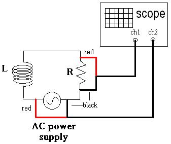
2. Construct the circuit shown below. Note that this is different
from the book! Watch your red and black oscilloscope wires! When
using Channel 1 and 2 simultaneously, it is important to have a common ground!
2. Vary the power supply voltage, but keep the frequency
constant, so V_R = const * V0
a. Turn the dial on the frequency generator
to 5000 Hz.
b. Set the VERT MODE to Ch. 2 to see the voltage from the AC power
supply. Turn the amplitude knob on the power supply until the max.voltage
you read is 1 V. This is V0.
c. Set the VERT MODE to Ch. 1 to see the voltage across the resistor.
Record this voltage. This is V_R.
d. Repeat steps b and c. for V0 = 2V, 3V, 4V, and 5V.
e. Make a graph of V_R versus V0, and get a regression line. Be
sure to include error bars!
3. Vary the frequency, but keep the power supply voltage constant.
a. Turn the Amplitude knob on the frequency
generator until V0 is 5V. The power supply voltage varies with frequency.
Unfortunately this is a feature of our frequency generators. You must
constantly watch the maximum voltage and keep it constant
at 5 V throughout this section.
b. Turn the frequency to 400 Hz. Check Ch. 2 to make sure V0
still has an amplitude of 5V. If not, change it back to 5V.
c. Turn the VERT MODE to Ch. 1. Record the voltage across the
resistor in the same way you did in (2.), above.
d. Record the angular frequency by determining the period of the wave
on your screen, and using the formula w = 2*pi/T
e. Repeat steps b, c, and d for frequencies: 800 Hz, 1200 Hz, 1600
Hz, 2000 Hz, 4000 Hz, 8000 Hz, 12,000 Hz, 16,000 Hz, and 20,000 Hz.
If you are running out of time, you may wish to do only every other frequency.
Get my initials on your data sheet if this occurs.
f. Make a graph of V_R versus w. Fit the data to our equation.
How to do the fit:
1) Run Graphical Analysis (GA)
2) Enter data as usual
3) Double click on the graph window to get rid of connecting lines and add
error bars.
4) Click on the graph window to select that window
5) Go the the menu Analyze and select Automatic Fit.
6) In the formula field, enter:
y = 5 * R/ (R^2 + x^2*L^2 )^0.5
and click OK. 5V is the value of the power supply voltage, x is the
angular frequency, R is the natural frequency, and L is the inductance.
7) Enter R =100 to get the fit going in the right direction (else it will
run out of iterations before it can find a fit).
8) When the numbers stop changing, the fit is done.
9) If you are satisified with the fit, then select that fit; otherwise,
click the "try new fit" button.
The graph you get should give you good values for
L. Your data should also fit the function within error bars.
Answer these questions after your conclusion.
(5 points each):
1. EXPLAIN your answers for "expected current
directions" for Lenz's Law on the data sheet. Tell me why you picked
the current direction you did.
2. EXPLAIN your answers for "expected current
magnitude" for Faraday's Law on the data sheet.
(Please do not copy the lab manual's definition of Lenz's Law. "Because
of Lenz's Law" or "Because of Faraday's Law" is not a sufficient answer.)
3. I will give you the manufacturer's values
for N, A, and l in class; make sure you write them down. Calculate
the theoretical value of L for our inductor based upon the equation: L =
mu * N^2 * A / l . How does this value compare to the value
you got in part II?