Electric Field Mapping Lab
last updated Sept. 30, 2002

home | notes menu

Pre-lab:
The pre-lab and the instructions for the pre-lab are located at http://www2.hawaii.edu/~jmcfatri/labs/fieldprelab.html .

Objectives
Our goal in this exercise is to map the electric field lines and equipotential lines of the following configurations:
      1.    Parallel Plate Capacitor
      2.    Cylindrical Capacitor
      3.    Electric Dipole
In addition, we will find alpha = effective length / actual length of the parallel plate capacitor, and verify that it is approximately 1.5.

N otes on Chapter 5
pp 31 - 37 of your lab book


Recall from the first lecture that in order to map the electric field, we placed a positive charge, +q,  in this field and measured the force on the charge.  We moved the charge around, and drew some arrows showing the direction of the force.  We then said that the electric field strength at a particular point in space was equal to the electrostatic force divided by our test charge +q.  (E = F/q  or  F = qE).

Unfortunately, this turns out to be hard to do in real life.

What can we do if we want to find out what the electric field looks like for a particular charge configuration?

There is another way to map the electric field.  We can map the equipotential lines.  Equipotential means "same potential".  An equipotential line is a line for which the potential is constant for every point on the line.

What does an equipotential line have to do with the electric field?
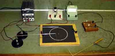
Answer:

Electric field lines are perpendicular to the equipotential lines at all points in space.
How do we measure the equipotential lines?  That's easy.  All we have to do is measure the voltage at all points in space.  The equipotential lines are all the points which have the same voltage.

As easy as this sounds, it is a little harder to do in practice.  To get the charge configurations, we will use a piece of  paper with silver conducting paint on it.  This paper that we are using is a special kind of paper called Teledeltos paper, which will allow current to flow in the direction of the electric field when a potential is applied to it.  We will construct the circuit shown, and place the 0 V and 10 V leads on the silver paint.  The potentiometer (or helipot as it is called in the manual) is a variable resistor (we are allowed to change the resistance of the resistor).  The potential of the middle lead of the potentiometer depends on the resistance which you have set it to.  Let's call the potential of the middle lead V1.  The potential at the probe is the potential of the paper at that point; let's call that V2.  If V1 = V2, then no current will flow through the ammeter.  If there is a potential difference, then current will flow.  If we set the potentiometer voltage V1 to 2 V and we observe no current in the ammeter, then we can say that V1 = V2 = 2 V.


Procedure:

1.    Obtain:
1 sheet of carbon paper
1 of each of the Teledelos papers
1 sheet of white copy paper
5 black or red wires with the fork on the end (in the cardboard box)
2 banana connectors
Part I: Cylindrical Capacitor

2.    Construct the circuit as shown below. See circuit diagram on page 32 for more information.

  setup
 
3.    Place the white copy paper on your board.  On top of that, place the carbon copy paper (black) face down, and place one of the Teledeltos papers face up (with the silver lines on the top).
4.    Mark the location of the silver lines by tapping the paper with a pen.  The carbon copy paper will make a mark on the white paper when you do this.
5.    Place the 0 V lead on one of the silver lines.  Set the 10 V lead on the other silver line.
6.    Turn on the power supply and set it to 10 V.
7.    Turn the potentiometer (helipot) to 2.0 V on the dial.  Place the probe on the paper at any point (other than the silver lines).
8.    Hold down the coarse adjustment key (marked "1").  The switch is shown below. You must hold this down until you have completed the coarse reading.

the switch
9.    Determine where the current is approximately zero.
10.  Fine tune the location by releasing the coarse key and holding down the fine adjustment key (marked "2").
11.  Mark the location by tapping lightly on the probe with a pen.
12.  Repeat steps 8-11 for the 4 V, and 6 Vsettings on the potentiometer.

Part II:
Repeat for the 
electric dipole, but only find the 2, 4, 6, and 8 V lines .

Part III:
Repeat for the parallel plate capacitor, but find the 2, 4, 5, 6, and 8 V lines. Also be sure to take the 4 and 6 V lines very carefully (about 1 cm between measurements) from one end of the paper to the other. Move the paper holders if you need to.

**  For the parallel plate capacitor only: **
Measure the length of the capacitor plate (l) and the distance between them (t)
Find the constant alpha, which is:

alpha = t * sumv / (10 V * l)
where the sumv = the sum of Ey * dx
You can find Ey and dx by dividing the x axis into 1 cm intervals on the 5 V line.  If you do so, dx = 0.01 m (or 1 cm).  Recall that Ey = -dV / dy, where dV = 2 V (the change in voltage, and dy = the distance between the 4 V and 6 V line.  Add all the Ey at each 1 cm division.  Sumv = your sum * 0.01 m. 

Data: You may use the data table on page 37 if you wish.
x distance,
starting at left hand side of paper
(cm)
distance between 6 and 4 V lines
dy
(     )
y-component of E
(     )

1


2


3


4


5


6


7


8


9


10


11


12


13


14


15


16


17


18


19


20


21


22


23


24


25


26


27


28


29


Actual length (l): __________+/-________
Thickness(t): __________+/-________
Effective length: __________+/- ________
Alpha: __________+/- ________

Assignment:
1. What is the meaning of the "effective length" of a capacitor? Why is this length longer than the actual length of the capacitor?