Circuit
Element
Photo
of Element
Circuit
Symbol
Description
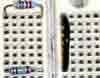
Wire
A circuit
element used to connect other circuit elements. Assume that wires
have no resistance.
Resistor
A resistor
is has many uses. In this class, it is used as a protective or dissipative
device. The resistance, measured in Ohms, can be found by looking
at the color bands.
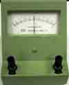
Battery
A battery
is a DC voltage source. The long line means + side.